
Content
- Hardware configuration
- Test description
- iMX6 Tiny Rex Quad with enclosure
- iMX6 Tiny Rex Quad - Bare Board
- iMX6 Tiny Rex Solo - Bare Board
- How to prepare the test
- Test script
Hardware configuration
Connected cables & devices
- Power jack: we used this +5V power adapter (you can buy it here, the original datasheet can be found here)
- SD card (Sandisk) preloaded with Filesystem, used for booting and for read/write test
- 1m CAT-5E Ethernet: loopback cable connected. Forced to 100Mb and used for ping test or to control the board via SSH session.
- HDMI monitor: during the HDMI test, a monitor is connected through 1.8m HDMI cable, but the monitor is not plugged into mains. Note: This option is used when HDMI input is not tested.
- HDMI loopback: when HDMI input is tested, it connects to the iMX6 Tiny Rex HDMI output via a shielded 1m HDMI micro to HDMI cable
- 2x USB memory stick: each USB memory stick is connected through a 2m long USB extension cable. Both USB memory sticks are used during the read/write test.
- USB micro to USB adapter: iMX6 Tiny Rex USB micro connector is set as a host and it is used during USB memory stick read/write test
- Wifi PCIE mini card: inserted, but not actively used. No antennas connected.
- Debug cable: FTDI TTL-3V3 UART to USB cable, used only to setup the board, not used and not plugged in during the measurements
- Mating connector for Peripheral Header: used for setting up initial HDMI input configuration, not used during the test.
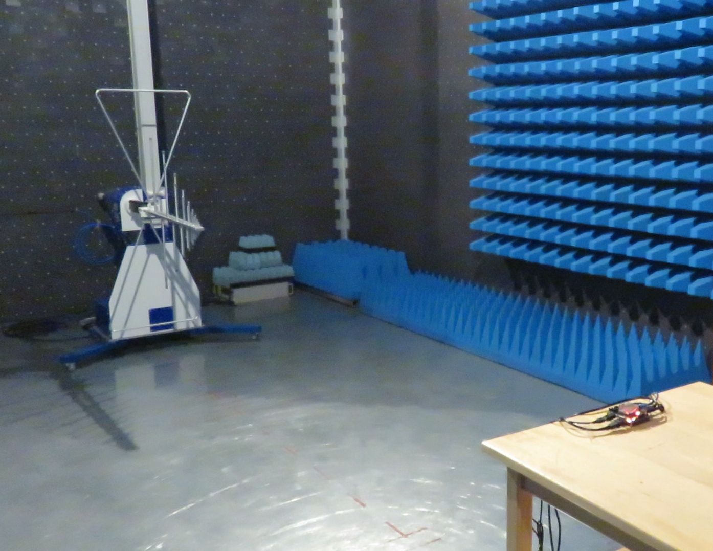
Test description
The main purpose of testing was to measure Radiated emission of iMX6 Tiny Rex when the board is running under heavy load. Following tests were running during the measurement:- CPU stress test
- Memory stress test
- HDMI output (Running 1920x1080 full-HD X windows Linux GUI and playing a video file)
- SD card test (read & write)
- 2x USB test (USB memory stick read & write)
- Ethernet ping (or SSH session)
- HDMI Output connected to on board HDMI Input
The results
iMX6 Tiny Rex Quad with enclosure
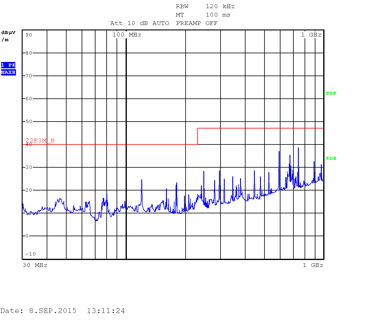
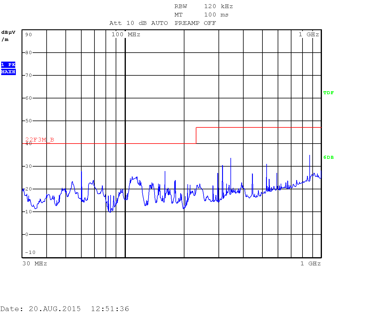
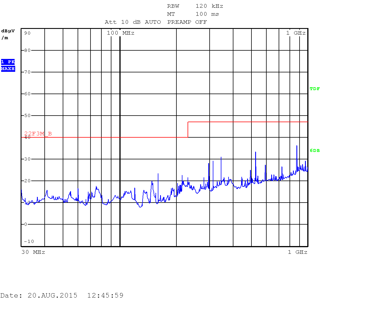
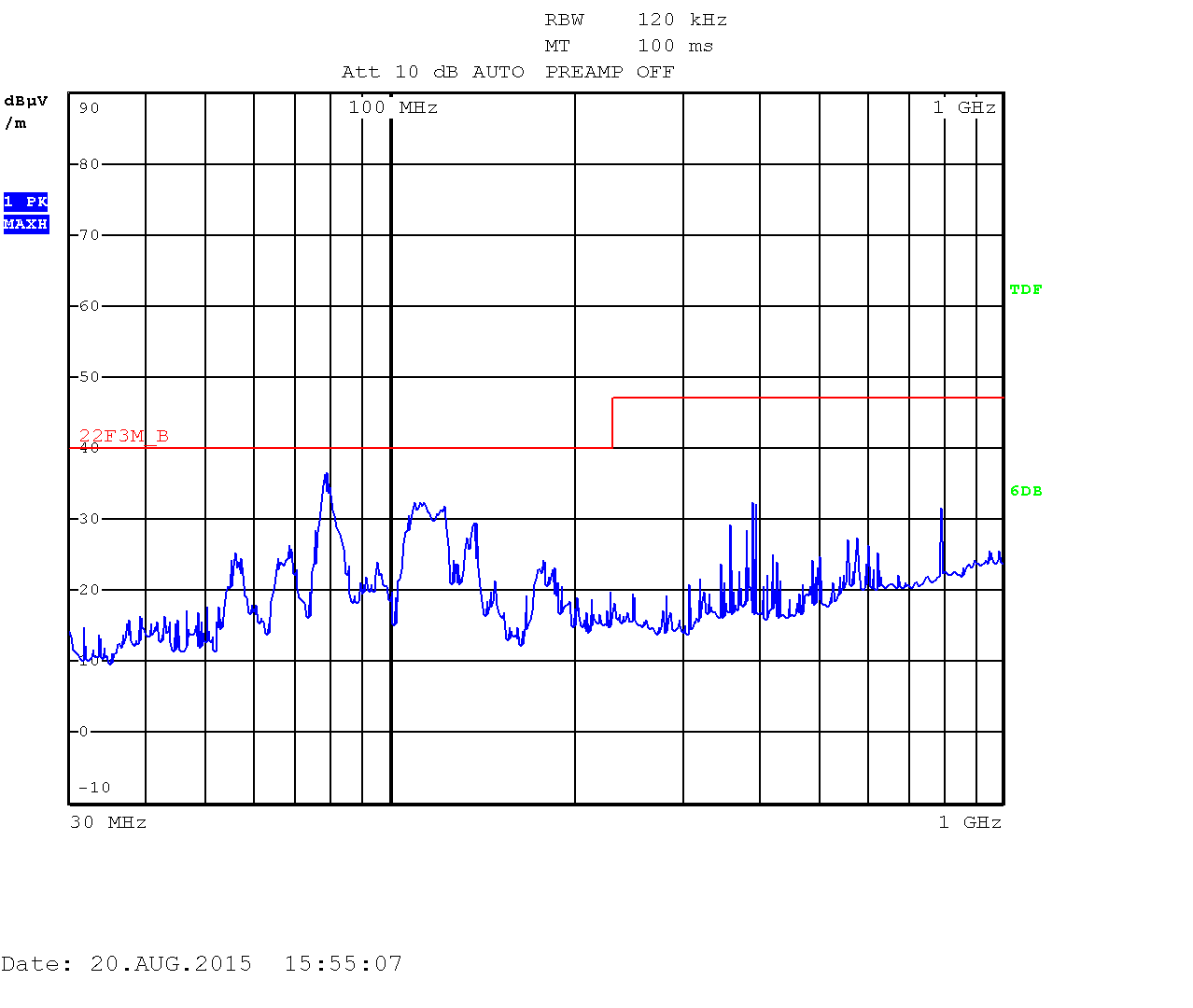
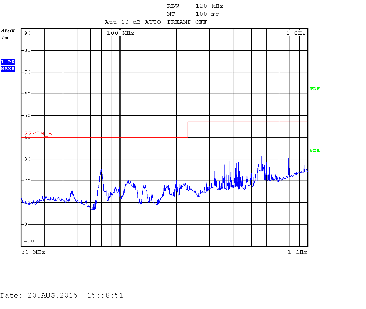
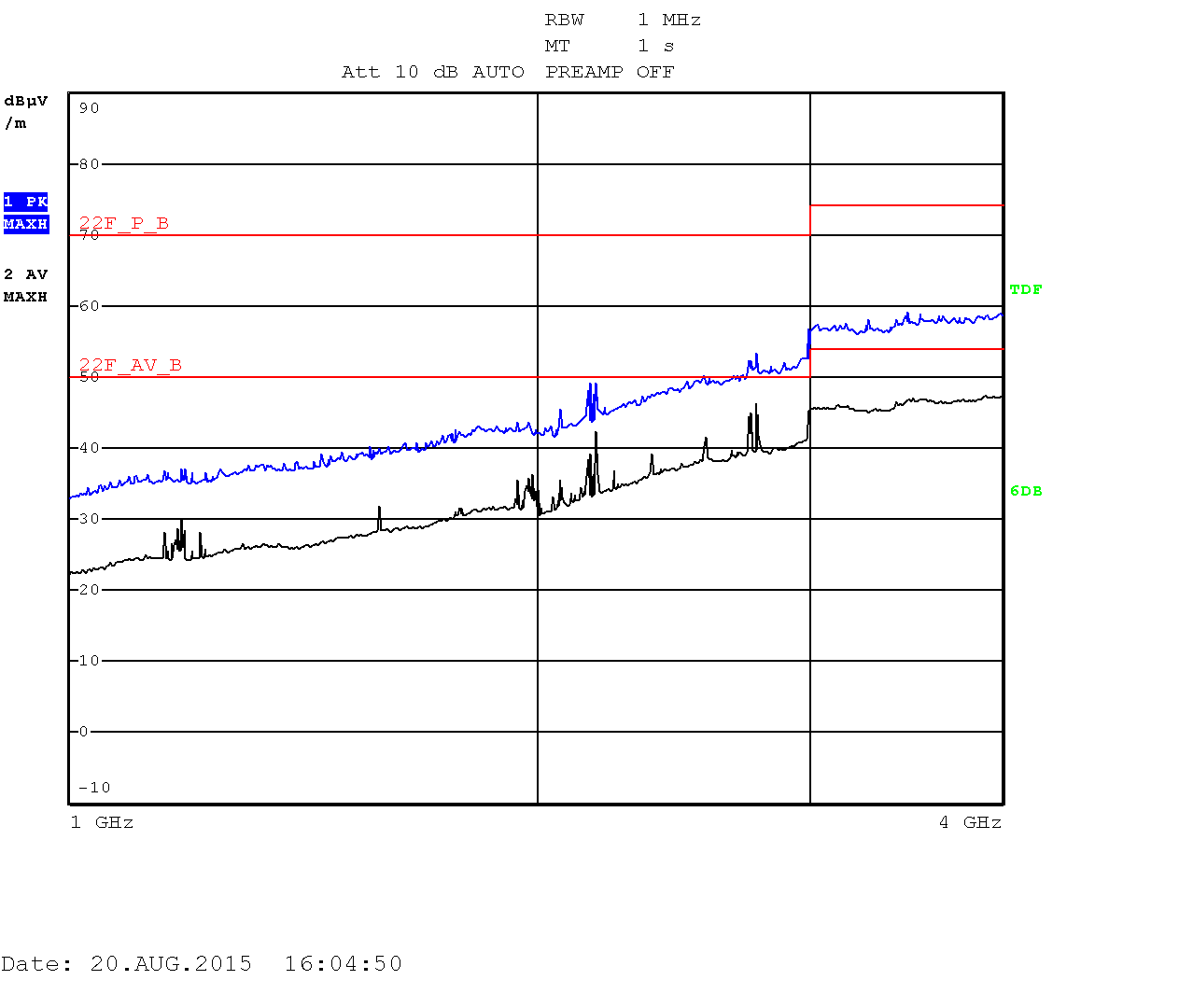
The setup passing through FCC CLASS B: iMX6 Tiny Rex + Lite Baseboard, 2x USB memory stick, HDMI output connected to HDMI input, Ethernet loopback, Switching power supply, enclosure, running heavy testing script for USB and SD card read/write test, stressapptest for CPU and memory, HDMI output & HDMI input in 1920×1080, Ethernet SSH session.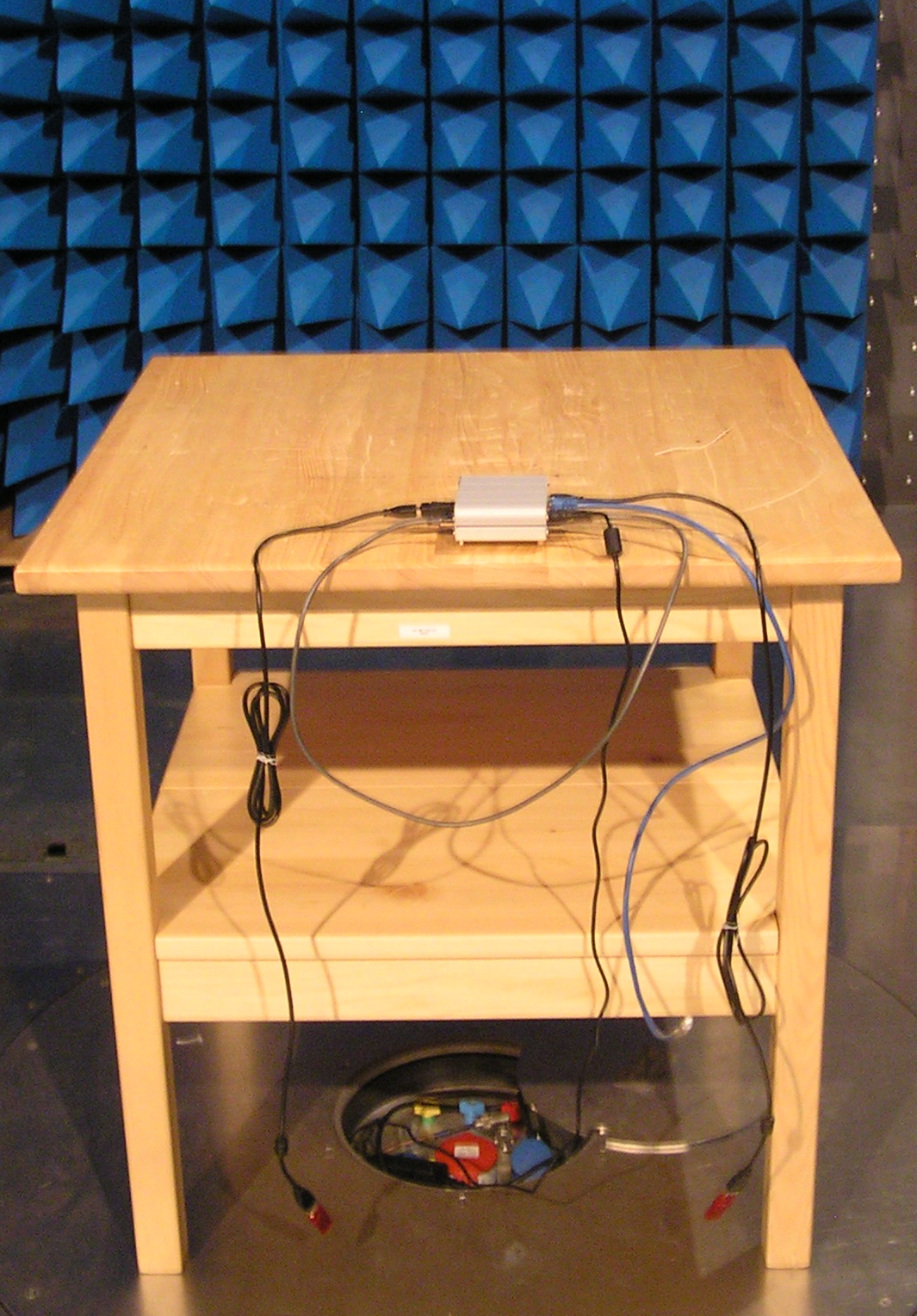
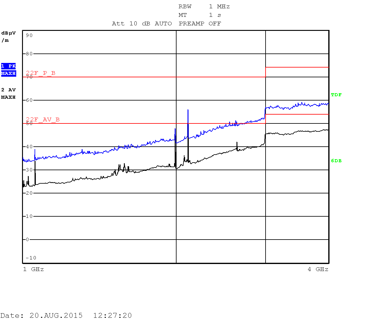
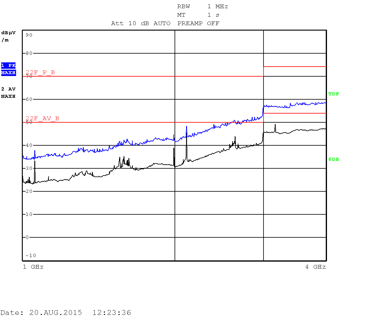
The measurements are displayed as quasi-peak value by default. For the higher band (above 1GHz) there are two plots displaying the power density. The blue curve represents the quasi-peak value. The higher limit (22F_P_B) is used for this type of measurement. The lower limit (22F_AV_B) is devoted to average-power measurement (shown with the black curve).
| Vertical polarization | Horizontal polarization |
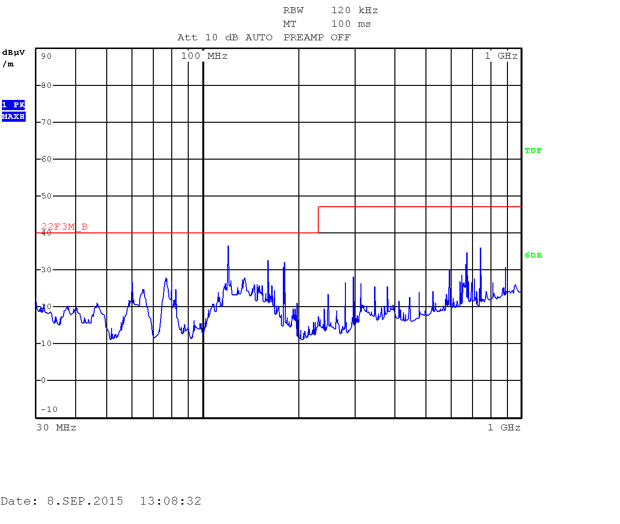
Heavy testing Quad CPU with an enclosure: 30kHZ - 1GHz
|
Heavy testing Quad CPU with an enclosure: 30kHZ - 1GHz
|
| Vertical polarization | Horizontal polarization |
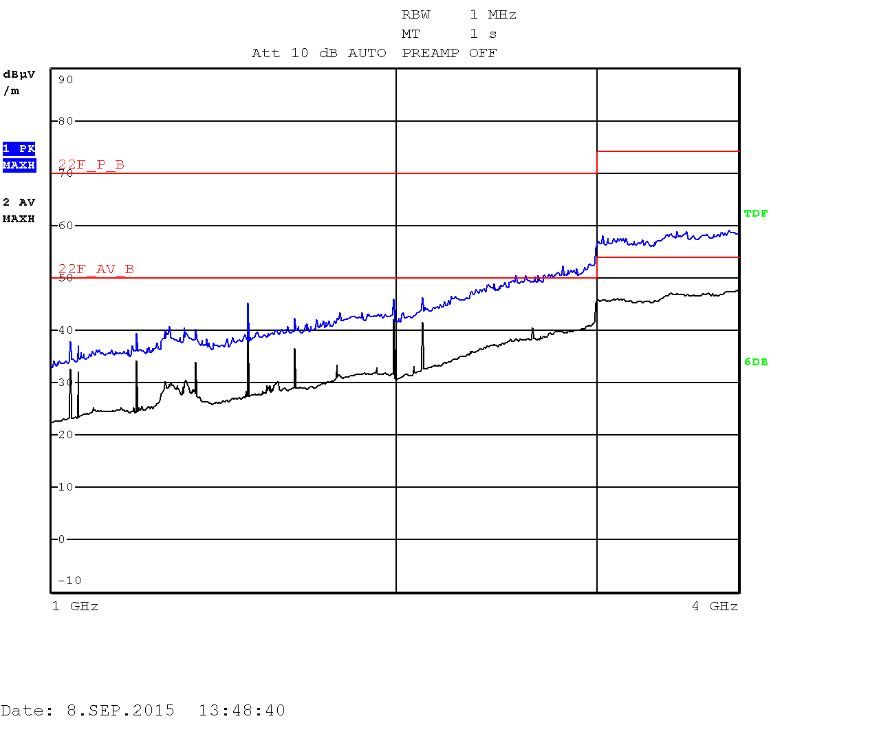
Heavy testing Quad CPU with an enclosure: 1GHZ - 4GHz
|
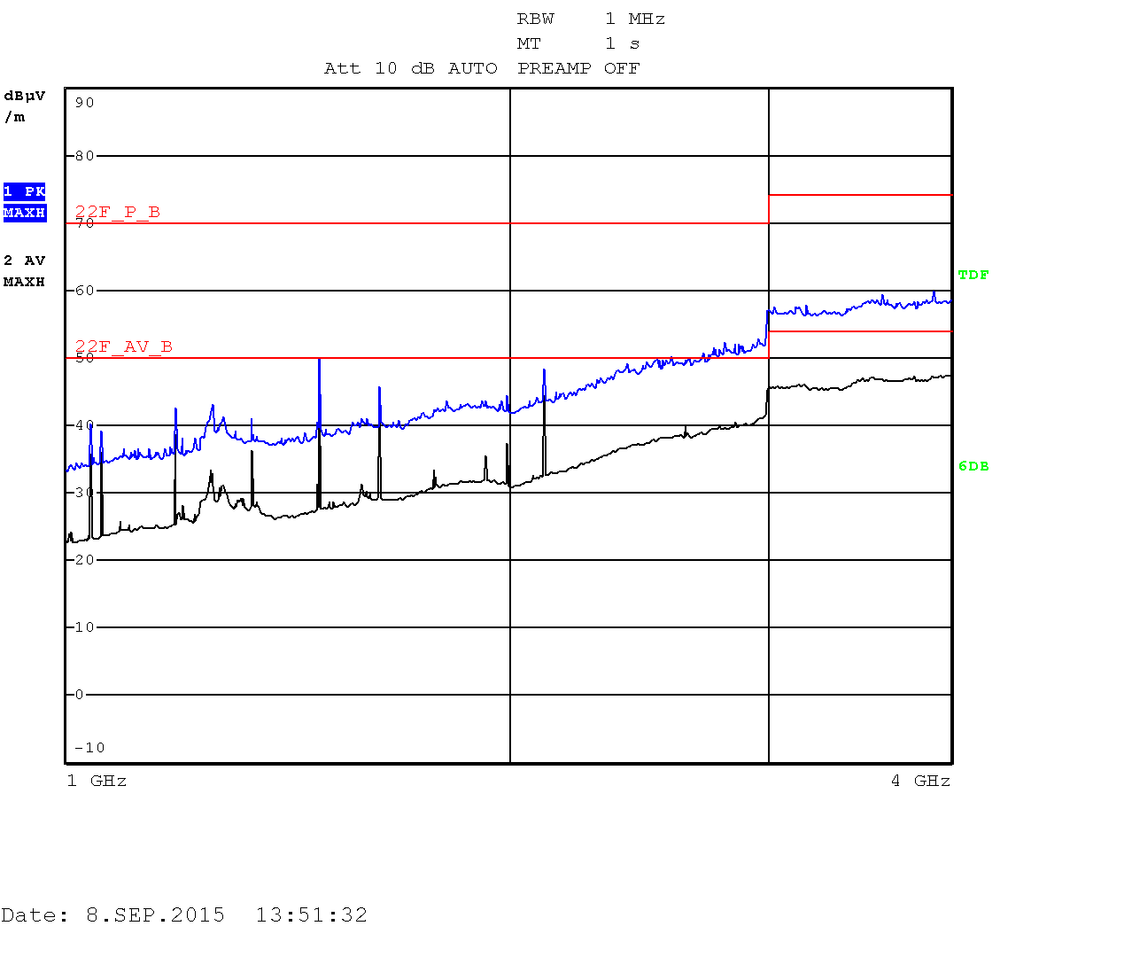
Heavy testing Quad CPU with an enclosure: 1GHZ - 4GHz
|
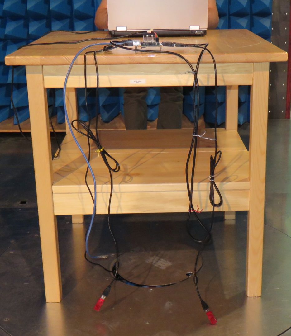
iMX6 Tiny Rex Quad - Bare Board
The bare board, with no enclosure, can easily pass FCC Class B (iMX6 Tiny Rex + Lite Baseboard, 2x USB memory stick, HDMI output connected to Monitor, Ethernet loopback, Switching power supply, no enclosure), but you need to be very careful about HDMI input and SATA (HDMI input and SATA were not connected during this measurement).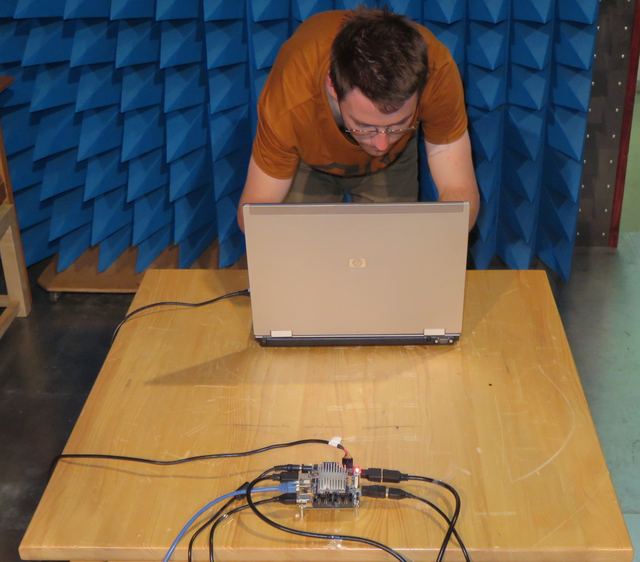
| Vertical polarization | Horizontal polarization |
Heavy testing Quad CPU: 30kHZ - 1GHz
|
Heavy testing Quad CPU: 30kHZ - 1GHz
|
| Vertical polarization | Horizontal polarization |
Heavy testing Quad CPU: 1GHZ - 4GHz
|
Heavy testing Quad CPU: 1GHZ - 4GHz
|
iMX6 Tiny Rex Solo - Bare Board
We tested also a board with i.MX6 Solo processor and a half of the memory chips (two chips instead of four chips were fitted). The script & setup used during this testing was the same as for iMX6 Tiny Rex Quad - Bare Board test.| Vertical polarization | Horizontal polarization |
Heavy testing Solo CPU: 30kHZ - 1GHz
|
Heavy testing Solo CPU: 30kHZ - 1GHz
|
| Vertical polarization | Horizontal polarization |
Heavy testing Solo CPU: 1GHZ - 4GHz
|

Heavy testing Solo CPU: 1GHZ - 4GHz
|
Appendix
How to prepare the test
1. We used our standard filesystem, with our default Linux kernel 3.0.5.. You can follow these steps if you want to create a bootable SD card.2. Insert the prepared SD card to the SD card slot.
3. Update the u-boot to boot up from SD card and set few other parameters. Note: During the test you may try to change the resolution.
setenv bootargs_mmc 'setenv bootargs ${bootargs} ip=dhcp root=/dev/mmcblk0p1 rootwait video=mxcfb0:dev=hdmi,1920x1080M@60,if=RGB666 vmalloc=400M fbmem=28M fbcon=28M'
setenv bootcmd_mmc 'run bootargs_mmc ; mmc dev 1; ext2load mmc 1 0x10800000 imx6rex 3915972; bootm 0x10800000'
setenv bootargs 'console=ttymxc0,115200'
setenv bootcmd 'run bootcmd_mmc'
saveenv
4. For HDMI Input test, you will need to configure the encoder chip first. We used a simple I2C initializations script and uploaded it by using i2c Linux tool. Before you can run the script, bypass I2C2 with I2C3 bus (in the particular kernel, I2C3 is not initialized). You can make a simple cable plugged into J17 with following shortened pins: J17-10 with J17-13 and J17-11 with J17-14. Then run this script:
#!/bin/sh

# iMX6 Tiny Rex test for EMC measurement

mountDevice() {
  mount /dev/$1 /media/$2
  cat /etc/mtab | grep -F "/dev/$1 /media/$2"
  if [ "$?" -eq "0" ]; then
    echo "$2 mounted"
  else
    echo "$2 not mounted"; exit 2
  fi
}

# mount devices
#mountDevice $1 sata
mountDevice $2 usb0
mountDevice $3 usb1
mountDevice $4 mmc0

finish_test_now() {
  echo "$(date +\%Y/\%m/\%d-\%T)($(date +\%Z)) Ctrl+C Detected: End of the test"
  $precced=0;
  kill -INT $vid_pid $str_pid $ping_pid $top_pid;
  exit;
}

#Reading of CSI input signals state

echo 146 > /sys/class/gpio/export #CSI0_PIXCLK
echo 149 > /sys/class/gpio/export #CSI0_VSYNC
echo 147 > /sys/class/gpio/export #CSI0_HSYNC

echo 91 > /sys/class/gpio/export #CSI0_D0
echo 90 > /sys/class/gpio/export #CSI0_D1
echo 95 > /sys/class/gpio/export #CSI0_D2
echo 94 > /sys/class/gpio/export #CSI0_D3

echo 150 > /sys/class/gpio/export #CSI0_D4
echo 151 > /sys/class/gpio/export #CSI0_D5
echo 152 > /sys/class/gpio/export #CSI0_D6
echo 153 > /sys/class/gpio/export #CSI0_D7
echo 154 > /sys/class/gpio/export #CSI0_D8
echo 155 > /sys/class/gpio/export #CSI0_D9
echo 156 > /sys/class/gpio/export #CSI0_D10
echo 157 > /sys/class/gpio/export #CSI0_D11

echo 158 > /sys/class/gpio/export #CSI0_D12
echo 159 > /sys/class/gpio/export #CSI0_D13
echo 160 > /sys/class/gpio/export #CSI0_D14
echo 161 > /sys/class/gpio/export #CSI0_D15
echo 162 > /sys/class/gpio/export #CSI0_D16
echo 163 > /sys/class/gpio/export #CSI0_D17
echo 164 > /sys/class/gpio/export #CSI0_D18
echo 165 > /sys/class/gpio/export #CSI0_D19

# kill all processes if Ctrl+C is detected
trap finish_test_now 2

# tell the X applications where they should run
export DISPLAY=:0

# run X window - wait for the process
service lightdm start

# connect ethernet loopback and force the ethernet to 100Mbit
mii-tool -F 100baseTx-HD

# stressapptest - one thread CPU, one thread memory, sata testing
stressapptest -s 600000 -M 500 -m 1 -C 1 --printsec 10 &
str_pid=$!
echo "$(date +\%Y/\%m/\%d-\%T)($(date +\%Z)) Starting stressapptest with PID: " $str_pid

# play a video file in an infinite loop
echo 0 > /sys/class/graphics/fb2/blank
sudo -u "ubuntu" xfce4-terminal --geometry=90x20+860+10 -x mplayer -vo fbdev2:/dev/fb0 -vf scale -zoom -loop 0 -geometry 1024x768+860+370 /home/ubuntu/Clouds.avi > /dev/null 2>&1 &
#vid_pid=$!
#echo "$(date +\%Y/\%m/\%d-\%T)($(date +\%Z)) Starting video file playback with PID: " $vid_pid


# open window with a log file
#sudo -u "ubuntu" xfce4-terminal --geometry=80x140+10+10 -x tail -F emc-testing.log > /dev/null 2>&1 &
#log_pid=$!
#echo "$(date +\%Y/\%m/\%d-\%T)($(date +\%Z)) Starting printing out the log file with PID: " $log_pid


# ping
sudo -u "ubuntu" xfce4-terminal --geometry=40x40+10+10 -x ping 192.168.0.150 &
#ping 192.168.0.150 &
ping_pid=$!
echo "$(date +\%Y/\%m/\%d-\%T)($(date +\%Z)) Starting ping: " $ping_pid

# top
#sudo -u "ubuntu" xfce4-terminal --geometry=80x80+10+400 -x top &
#top_pid=$!
echo "$(date +\%Y/\%m/\%d-\%T)($(date +\%Z)) Starting top: " $top_pid

proceed=1
file1="blackbird.wav"
file2="blackbird2.wav"

cp1_from="/media/mmc0/"
cp1_to="/media/usb0/"

cp2_from="/media/mmc0"
cp2_to="/media/usb1/"

#copy files in case they are missing
cp /media/$file1 $cp1_from$file1
cp /media/$file1 $cp1_to$file1
cp /media/$file2 $cp2_from$file2
cp /media/$file2 $cp2_to$file2

while [ $proceed -eq 1 ]
do

clk=$i$(cat /sys/class/gpio/gpio146/value) #CSI0_PIXCLK

vs=$(cat /sys/class/gpio/gpio149/value) #CSI0_VSYNC
hs=$(cat /sys/class/gpio/gpio147/value) #CSI0_HSYNC

c=$(cat /sys/class/gpio/gpio155/value) #CSI0_D9
c=$c$(cat /sys/class/gpio/gpio154/value) #CSI0_D8
c=$c$(cat /sys/class/gpio/gpio153/value) #CSI0_D7
c=$c$(cat /sys/class/gpio/gpio152/value) #CSI0_D6
c=$c$(cat /sys/class/gpio/gpio151/value) #CSI0_D5
c=$c$(cat /sys/class/gpio/gpio150/value) #CSI0_D4
c=$c$(cat /sys/class/gpio/gpio94/value) #CSI0_D3
c=$c$(cat /sys/class/gpio/gpio95/value) #CSI0_D2
C=$(echo "ibase=2;obase=A;$c" | bc)

y=$(cat /sys/class/gpio/gpio165/value) #CSI0_D19
y=$y$(cat /sys/class/gpio/gpio164/value) #CSI0_D18
y=$y$(cat /sys/class/gpio/gpio163/value) #CSI0_D17
y=$y$(cat /sys/class/gpio/gpio162/value) #CSI0_D16
y=$y$(cat /sys/class/gpio/gpio161/value) #CSI0_D15
y=$y$(cat /sys/class/gpio/gpio160/value) #CSI0_D14
y=$y$(cat /sys/class/gpio/gpio159/value) #CSI0_D13
y=$y$(cat /sys/class/gpio/gpio158/value) #CSI0_D12
Y=$(echo "ibase=2;obase=A;$y" | bc)

echo "$(date +\%Y/\%m/\%d-\%T)($(date +\%Z)) State of CSI0 signals:"
echo "C | V H | C[7:0] | Y[7:0]"
printf "%d | %d %d |   0x%02X | 0x%02X\n" $clk $vs $hs $C $Y


  cp1_done=`ps cax | grep $cp1_pid | grep cp`
  if [ -z "$cp1_done" ]; then # copy finished
    if cmp -s $cp1_from$file1 $cp1_to$file1; then
      echo "$(date +\%Y/\%m/\%d-\%T)($(date +\%Z)) PASS: Copying file from $cp1_from to $cp1_to successful"
    else
      echo "$(date +\%Y/\%m/\%d-\%T)($(date +\%Z)) ERROR: Difference between files on $cp1_from and $cp1_to detected"
    fi
	cp1_temp=$cp1_from # swap destinations
	cp1_from=$cp1_to
	cp1_to=$cp1_temp

	rm $cp1_to$file1 # remove destination file

    cp $cp1_from$file1 $cp1_to$file1 &
    cp1_pid=$!
    echo "$(date +\%Y/\%m/\%d-\%T)($(date +\%Z)) Started copying file from $cp1_from to $cp1_to"
  fi

  cp2_done=`ps cax | grep $cp2_pid | grep cp`
  if [ -z "$cp2_done" ]; then # copy finished
    if cmp -s $cp2_from$file2 $cp2_to$file2; then
      echo "$(date +\%Y/\%m/\%d-\%T)($(date +\%Z)) PASS: Copying file from $cp2_from to $cp2_to successful"
    else
      echo "$(date +\%Y/\%m/\%d-\%T)($(date +\%Z)) ERROR: Difference between files on $cp2_from and $cp2_to detected"
    fi
    cp2_temp=$cp2_from # swap destinations
	cp2_from=$cp2_to
	cp2_to=$cp2_temp

	rm $cp2_to$file2 # remove destination file

    cp $cp2_from$file2 $cp2_to$file2 &
    cp2_pid=$!
    echo "$(date +\%Y/\%m/\%d-\%T)($(date +\%Z)) Started copying file from $cp2_from to $cp2_to"
  fi

done