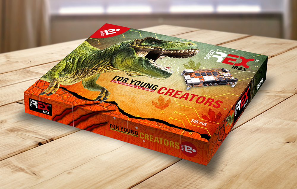
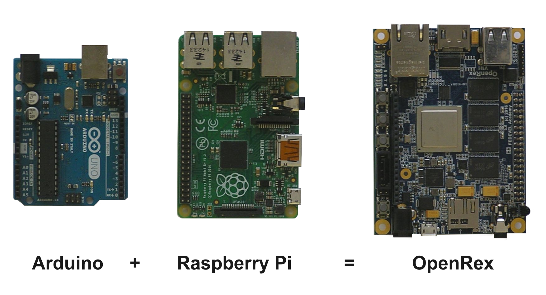
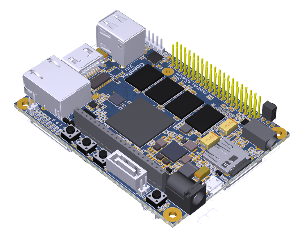
Designed for Playing, Learning and Hacking (by FEDEVEL)
Completely Open Source. Based on NXP (Freescale) i.MX6 CPU + LPC13xx MCU. Arduino & Raspberry Pi like headers. All documents are free for download, including Schematic and PCB.
Community
If you are a fan of OpenRex project or if you are using OpenRex board in your own project, please let us know through our OpenRex Education Project Community website. You can share your projects there, ask others for help or their opinion and, if you like, you can become member of a team creating & building awesome resources to help kids to learn programming and electronics. Have a look at openrexkit.org
Status
Available. Purchase OpenRex from VOIPAC >
Specification
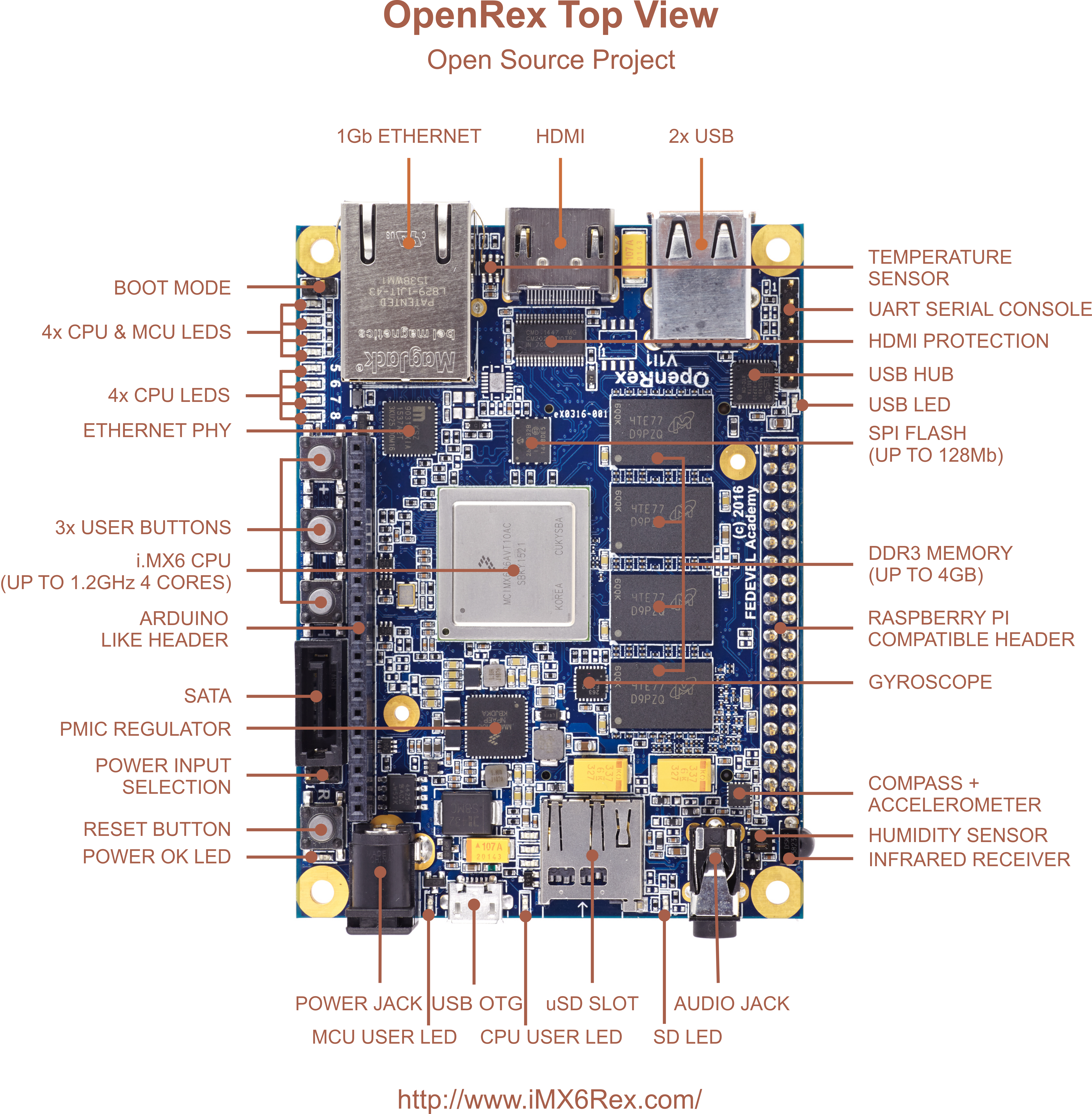
- NXP (Freescale) i.MX6 processor, up to 1.2GHz / 4 cores
- NXP microcontroller LPC13xx (Default: LPC1345FHN33)
- Soldered down DDR3-1066 (533MHz), up to 4GB
- 1x 10/100/1000 Mbps Ethernet
- 1x HDMI Output (up to QXGA 2048×1536)
- 1x Parallel CSI Camera input or RGB Parallel Display output
- 1x Differential Camera Input (Compatible with Raspberry Pi) or LVDS display output
- 1x SATA
- 1x micro SD
- 1x PCIE mini slot + micro SIM (can be used for WiFi or Wireless modem)
- 1x USB OTG Micro
- 2x USB
- 1x CAN transceiver
- 1x Compass + Accelerometer
- 1x Gyroscope
- 1x Humidity sensor
- 1x Temperature sensor
- 1x Audio (Headphones output, Microphone input)
- 1x Touchscreen connector (Touchscreen through LPC13xx / Optional 4x Analog input)
- 1x I2C EEPROM
- 1x SPI FLASH
- 1x IR Receiver
- 1x Arduino type header. Default:
- 4x Analog input
- 3x GPIO
- 1x I2C
- 1x CAN
- 1x USB
- 1x Raspberry PI type header. Default:
- 2x I2C
- 2x UART
- 1x CAN TX/RX
- 2x SPI
- 3x GPIO/PWM
- 1x UART Debug console (FTDI compatible)
- 8+2 USER LED
- Power LED, SD Card LED, USB HUB LED
- 1x Reset button, 3x User button (e.g. Home, Volume Up, Volume Down)
- Size: 70 x 95 mm (2.75 x 3.75 inch)
- Input power: 5V DC (through Power Jack or USB micro)
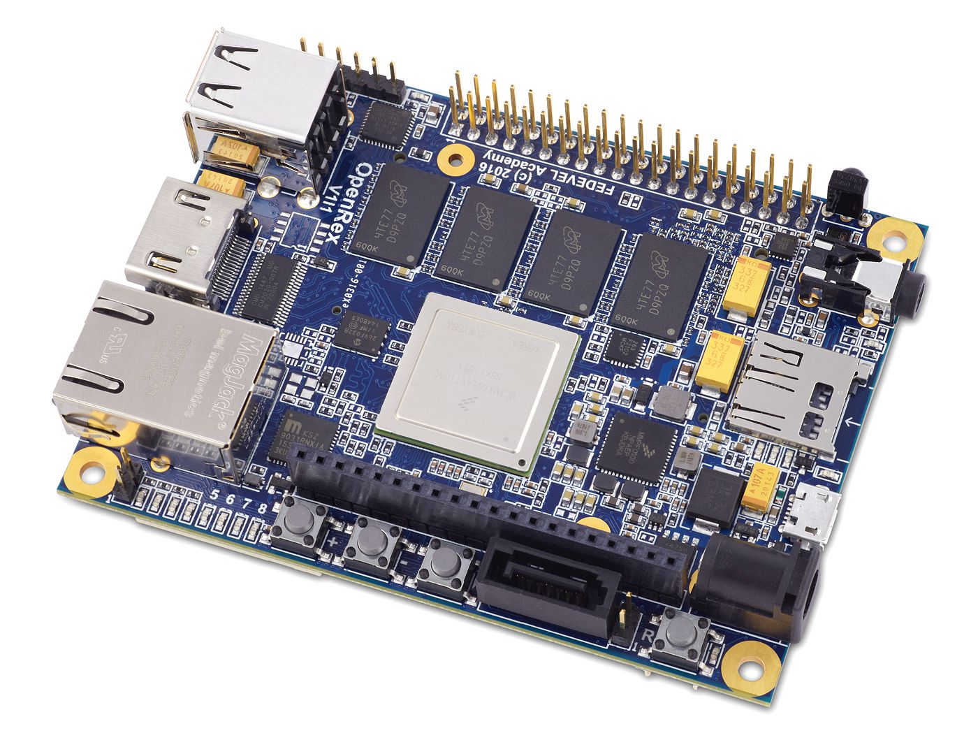
Board overview Top
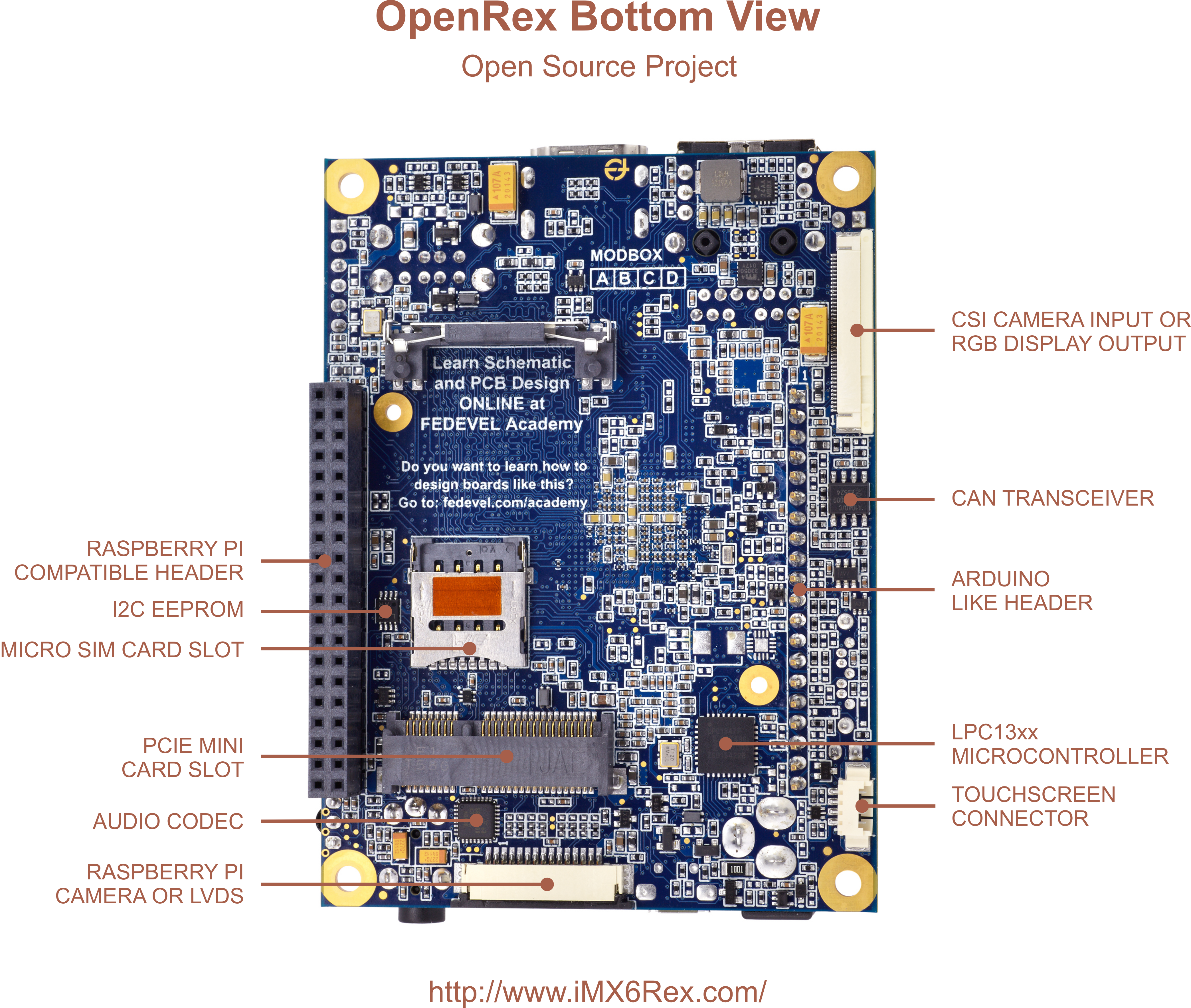
Board overview Bottom
Download Complete OpenRex Production & Altium Designer Files

Getting started
How to connect your OpenRex board for the very first time? Read here >
Datasheet
OpenRex datasheet was created by VOIPAC and can be downloaded here >
Software
To find out all about OpenRex software, click here >

Schematic
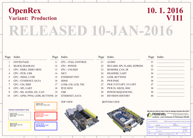 Download OpenRex schematic in PDF
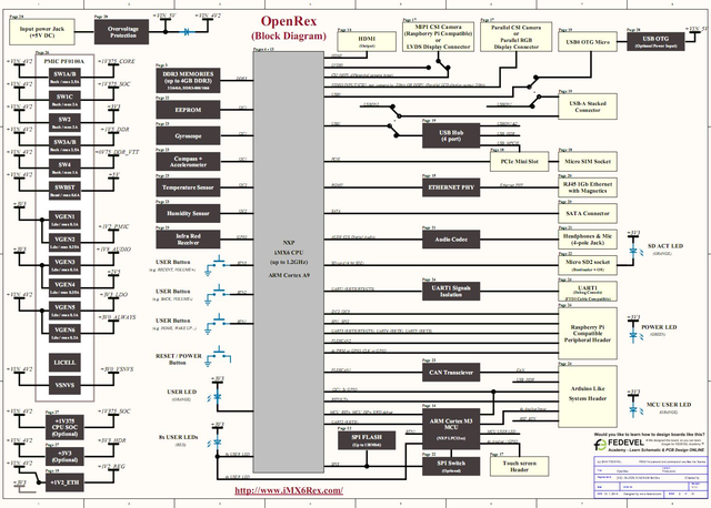
Block diagram
3D PDF
 This is the OpenRex 3D PDF (use Adobe Reader to see it)
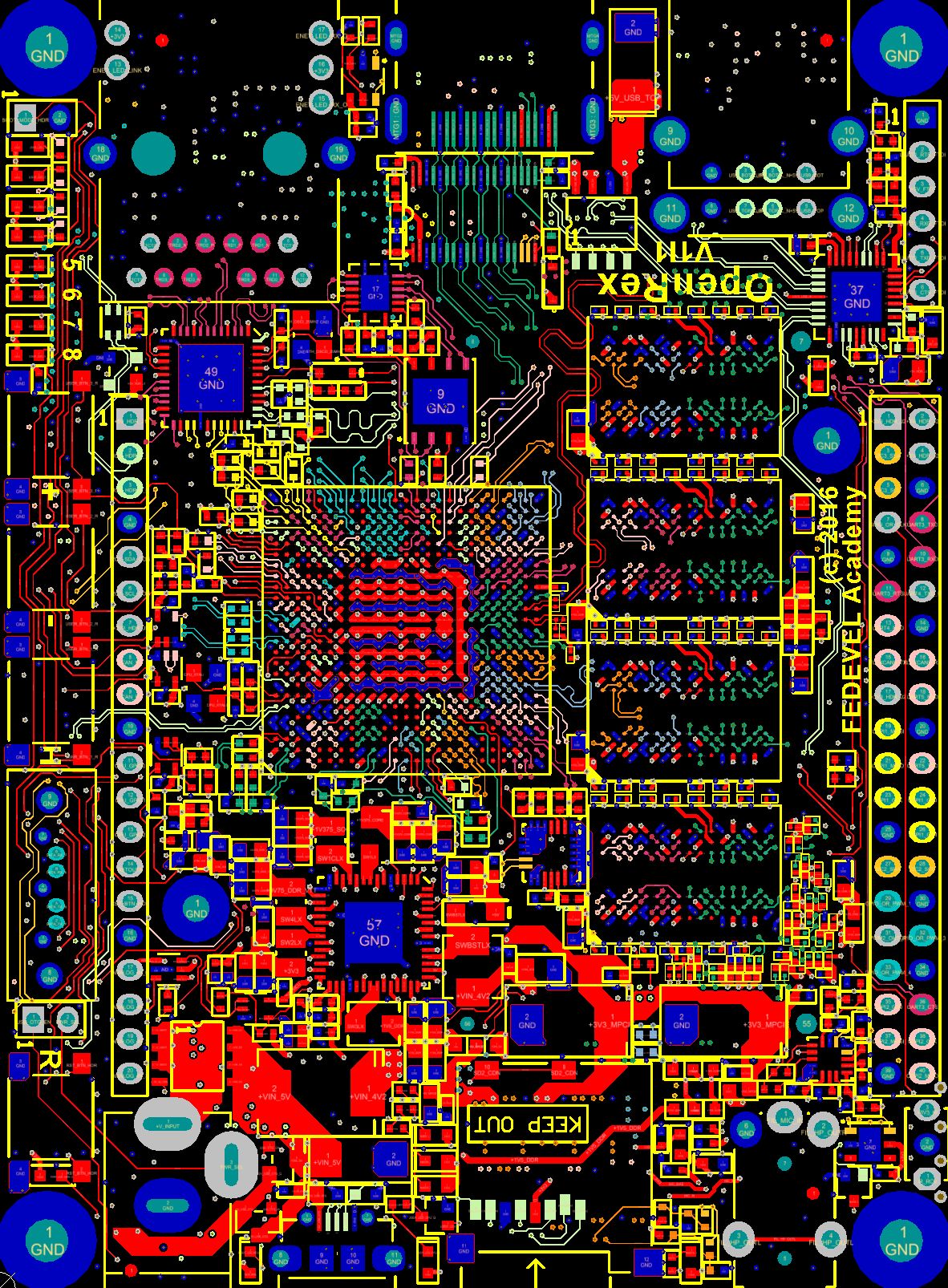
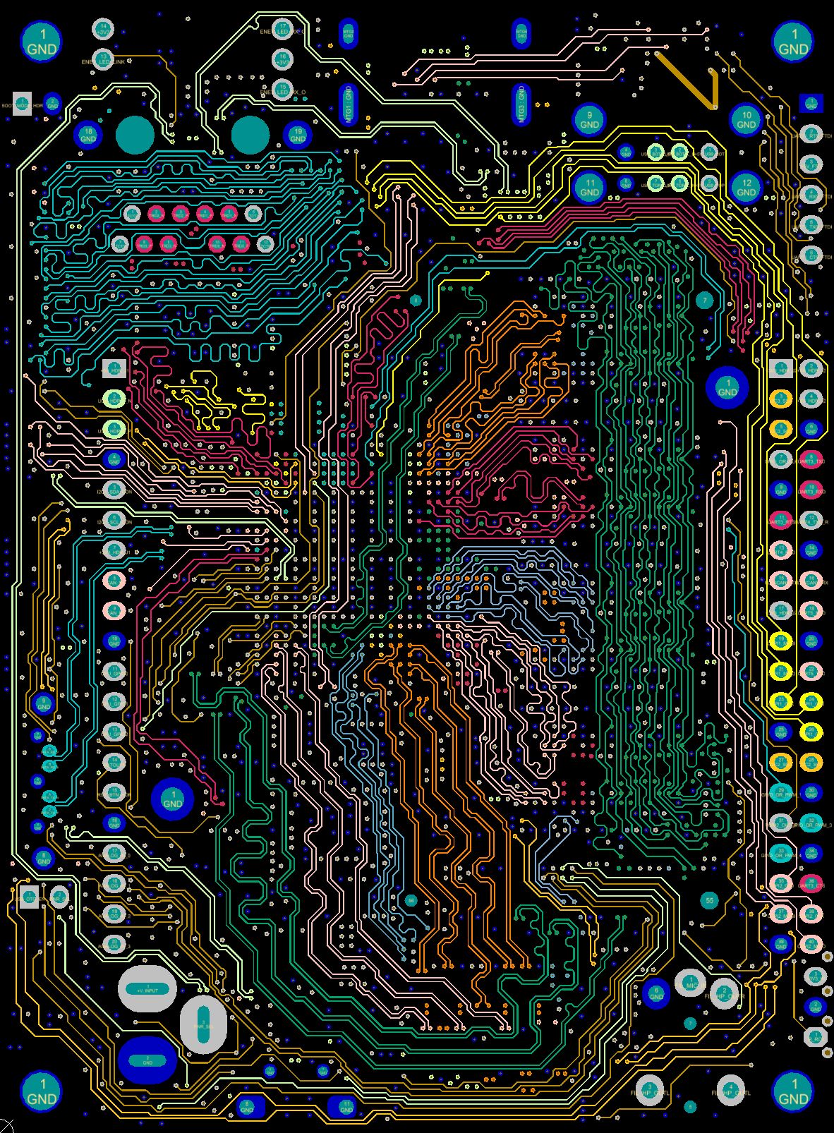
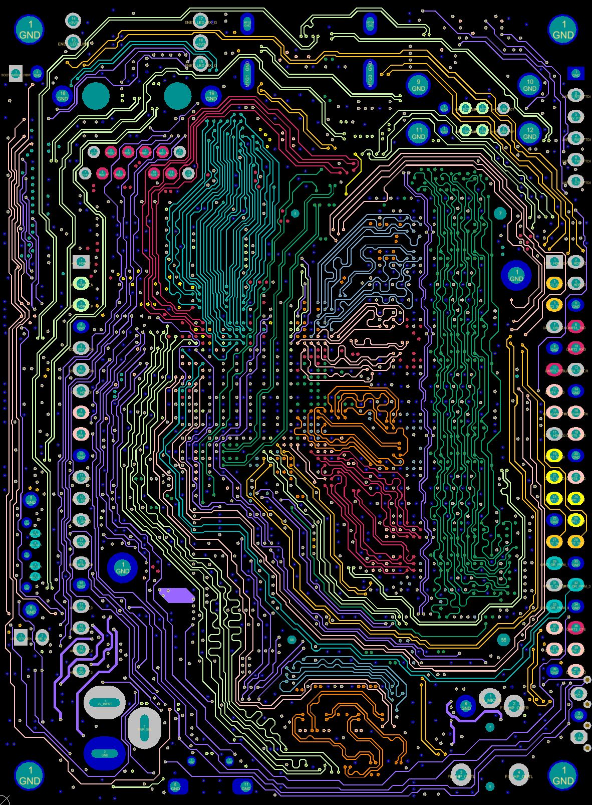
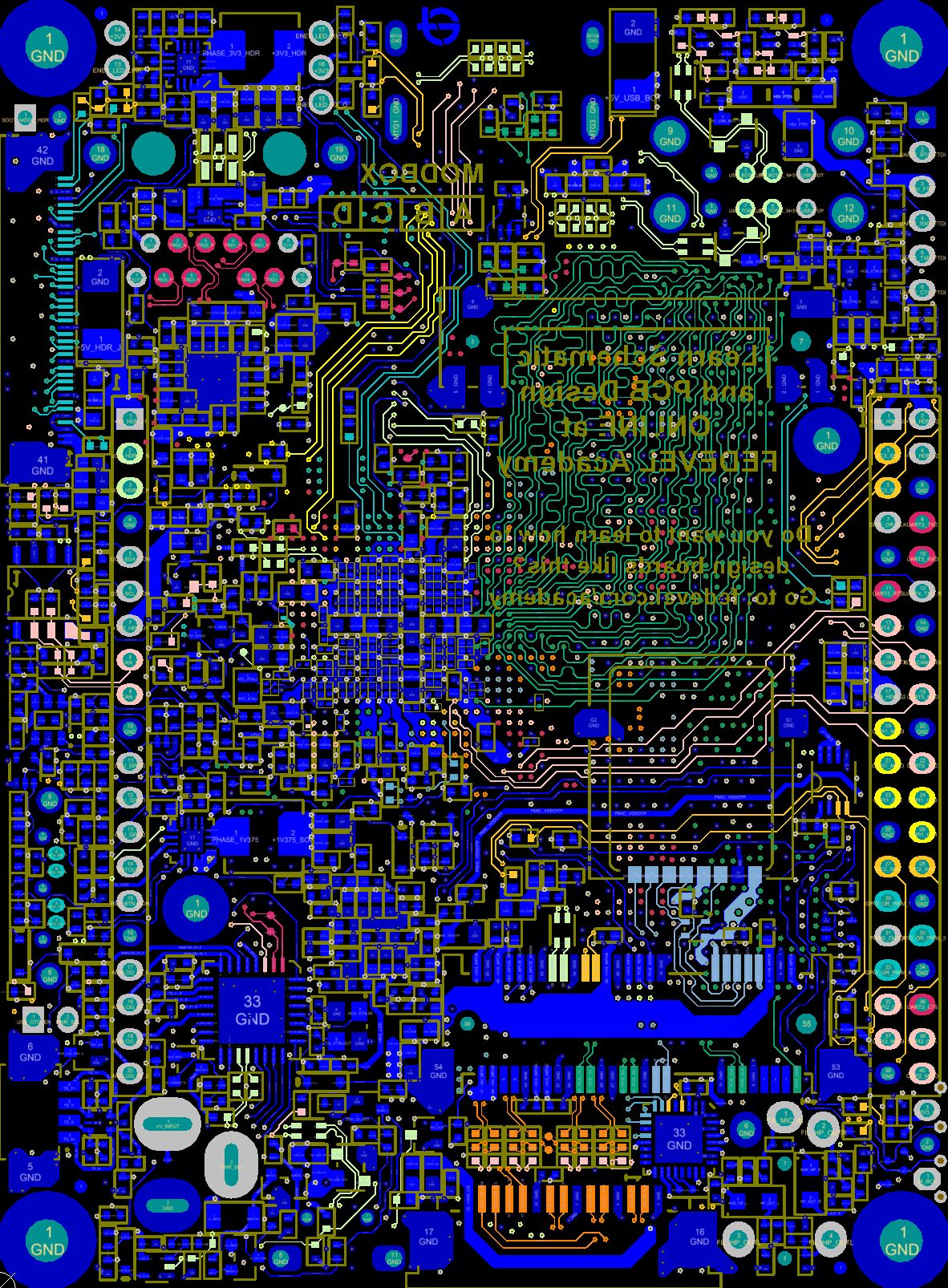
PCB Layout
Here are some screenshots from the signal layers of OpenRex PCB. The PCB has 10 Layers in total with through hole VIAs only.
|
|
|||
|
|
|
|
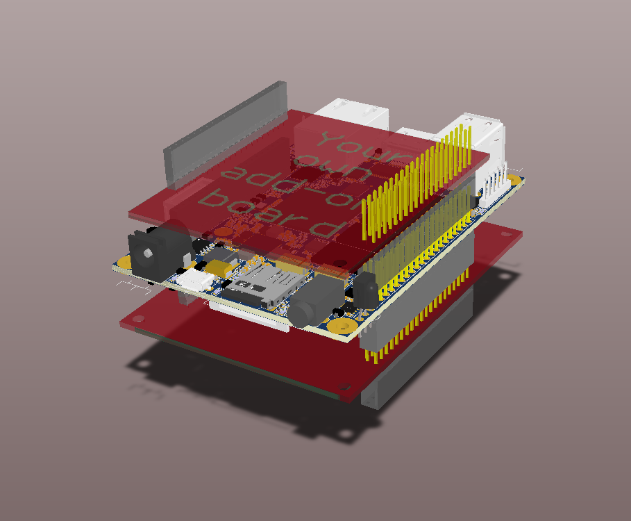
Add-on boards
The TOP OpenRex add-on board is also Raspberry Pi compatible. It may be used on the OpenRex SOLO version (with no or low profile heatsink). The BOTTOM add-on boards are larger. The plan is to support multiple add-on boards stacked on top of each other. It will require a lot of testing and playing ![]() Click here to download 3D PDF to see it in Adobe Reader.
Click here to download 3D PDF to see it in Adobe Reader.
Project status
When we test a new peripheral, we also update this table. More details about the tests can be found here >>
Releated posts
- Playing with OpenRex – Position visualization of OpenRex in 3D Software
- Programming NXP Microcontroller directly through WEB? Here we go …
- Would you like to control your board through a WEB interface?
- How to setup Webserver on OpenRex
- OpenRex is Alive!
- OpenRex Status Update
- OpenRex Schematic is now Available :)
Module License
OpenRex is completely free for personal & commercial use. This project is developed under Creative Commons Attribution 4.0 International license. There is only one exception: Using this project (in whole or in part) or its modifications for any commercial educational activities (e.g. paid courses, trainings, videos, ….) without express written permission of FEDEVEL is prohibited. Universities can use this project with no limitations.
Why this exception?
The income from FEDEVEL courses covers development of open source boards like this.